This subrack is typically used in Optical Fibre Termination activities, where low fusion splice losses are needed for high capacity optical fibre transmission systems, such as e.g. DWDM systems.
A major feature of this subrack is the minimum amount of movement that occurs to optical fibre loose tubes and optical fibre cords as the pivot tray opens and closes. This ensures a very high degree of protection for working services. Also, the rear located splice trays are housed in a protected position, because there is very little chance of them being disturbed, as the subracks tray is opened.
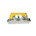
Splice/Splice LH pivot open Subrack (3RU), for 144 optical fibres, mid or rear mounts in a 19” rack
Maintains fibre bending radii throughout, for terminated optical fibres at 30mm
Supplied with 1 set of 12 high, 12 fibre, splice tray assembly (Part No: TC254S-12AX), for 144 fusion splices. One 12 fibre splice protector holder clip is located on each splice tray
A 50mm x 50mm duct length is provided to run fibres from RHS to LHS around the rear of the subracks body. This allows optical fibre cords to enter and leave from both the LHS and RHS front corners of the subrack
Adjacent to RHS front optical fibre cord entry port, is situated a guide to enable entering cords to flow smoothly onto the rear 50mm x 50mm duct
On the pivot tray adjacent to the RHS duct entry guide is a raised edge, and large aperture tie, intended to prevent optical fibre cords or protection/loose tubes entering the splice trays, from becoming caught by the duct entry guide.
RHS rear entry, cable break-out to loose tubes that flow along subracks rear (under the pivot trays raised area) and LHS of subrack, then onto splice trays, through large, smooth curves. Cable is secured at RHS entry point
Both the LHS and RHS entry/exit ports have 2 x 30mm radius guides for guiding optical fibre cords
The optical fibre cords are secured to the radius guides by hook and loop ties
A large guide bracket for protection/loose tubes and optical fibre cords is located on the pivot tray, near the pivot to guide entering optical fibre cords. This bracket guide has high narrow width side guides, to allow protection/loose tubes to flow to the splice trays in a large smooth curved path
Both are entering and outgoing protection/loose tubes and optical fibre cords are fastened by hook and loop style ties
Supplied with a centrally located four position patch panel, with A/SC through adapters (for emergency use only)
A/SC through adaptors have a ceramic zirconia sleeve
An easily accessible, hinged, record system is provided inside the front cover. Cover secured with magnetic catches
An accessory kit is provided, including hook and loop style ties
Heat shrink splice protectors (Part No: 100 x 080); available separately