Parallel fibre optic connectivity – 40G/100G solutions
News, HypaFOX MTP® - September 01, 2020

Upgrading to 40/100G with correct Polarity
In traditional (serial) optical communications, a transceiver on each end of a link contains one transmitter and one receiver.
For example, on a duplex channel, the transmitter on End A communicates with the receiver on End B and another optic fibre is connected between the transmitter on End B and the receiver on End A. This allows for 10G transmission signals to be sent and received over duplex LC links.
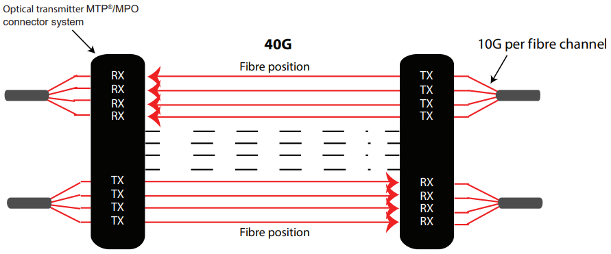
40G and 100G systems require a slightly different configuration with parallel optical communication.
In parallel optical communications, the devices on either end of the link contain multiple transmitters and receivers, which enables multiple fibres or lanes to be used to transmit and receive the same signal.
This type of connectivity utilises a ribbon cable type design with all fibres aligned in a straight array, in either a 12 fibre or 24 fibre configuration.
For instance, 40G uses four lanes/fibres on End A to communicate with End B. Therefore, the data stream is spread over the four optical fibres in each direction (8 fibres in total).
100G utilises ten transmitters on End A to communicate with ten receivers on End B. This spreads the data stream over the ten optical fibres in each direction (20 fibres in total).
Furthermore, 3 possible methods for 100G connectivity are available including:
- 1 x 24-fibre MTP®/MPO connector with the top centre 10 positions allocated to transmitting and bottom ten allocated to receiving.
- 2 x 12-fibre MTP®/MPO connectors side by side. The 10 positions in the centre of the connector on the left are used for transmitting and the centre 10 positions of the right are used for receiving.
- 2 x 12-fibre MTP®/MPO connectors, using a stacked layout. The ten centre positions of the top MTP®/MPO connector are used for receiving and the ten centre positions of the bottom MTP®/MPO connector are used for transmitting.

Array patch cords for 100G systems with 24 Fibre MTP®/MPO transceiver ports
Some 100G transmission equipment utilises a 1 x 24F MTP®/MPO port, instead of 2 x 12F ports for sending and receiving.
In these instances, a 24F ferrule MTP®/MPO connector is required to connect to the equipment. The opposite end is generally divided into separate 12F MTP®/MPO connectors, which connect to bulkhead adaptors and to the MTP®/ MPO trunk cable.
The various configuration options are listed below.


